Designing a 22V motor controller for the team's first fully electric car
The self-made brains of a car
As part of UTSM's Prototype Powertrain team, I helped to implement a
Collaborated alongside Andrew
Radke and Maya Edie-Maxsom in
the Prototype Powertrain team.
Tech Stack:
Layout planning
In the inital planning stages, a previous iteration of the motor controller PCB was used
to
create a model for how our motor controller would work. The choice to use a PCB was made
on the basis that the system needed to be small to fit inside a one-passenger racecar,
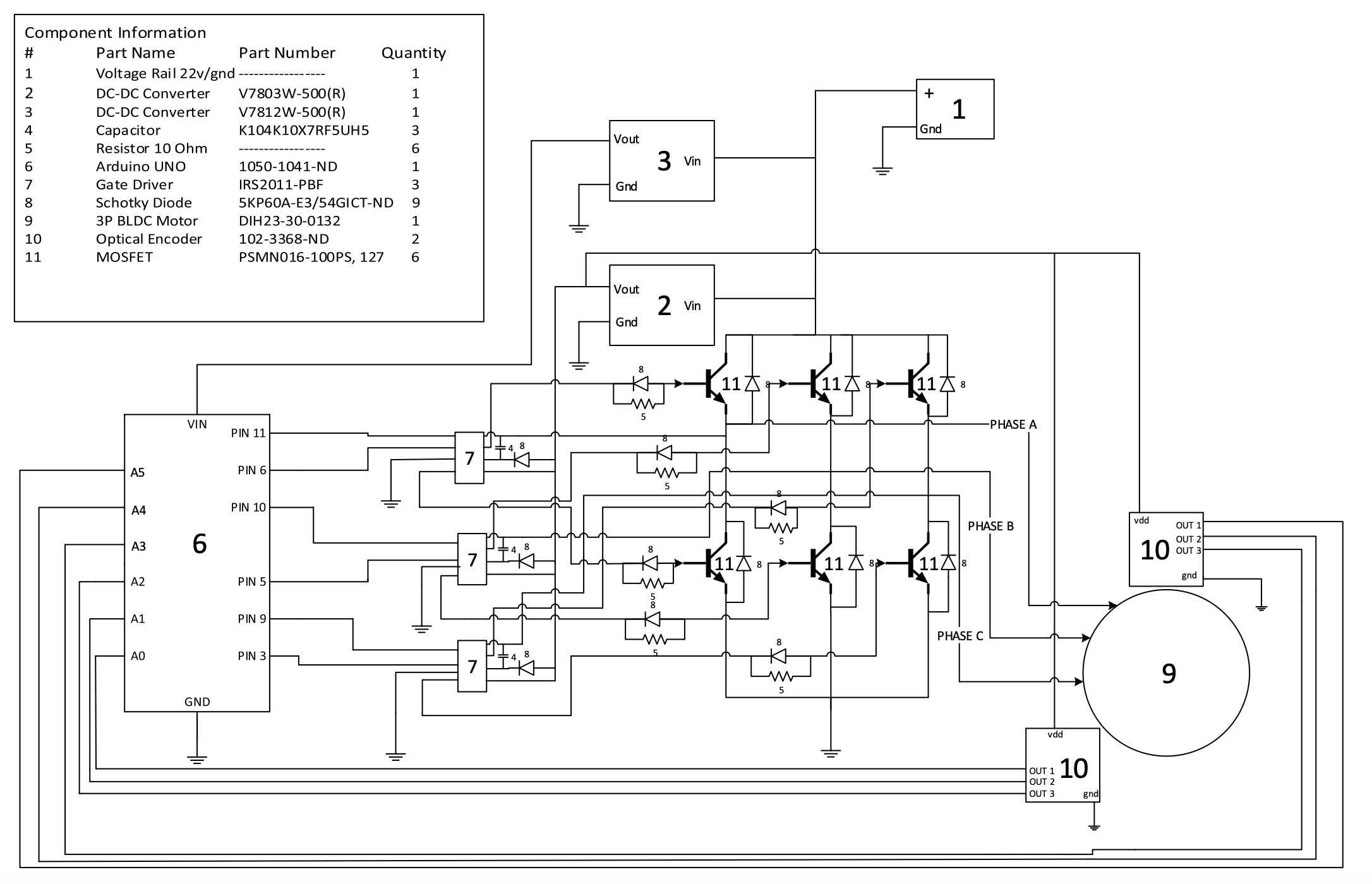
and because it would be able to supply high power. Using a combination of encoders,
drivers, an Arduino microcontroller, and other components, I started work on the motor
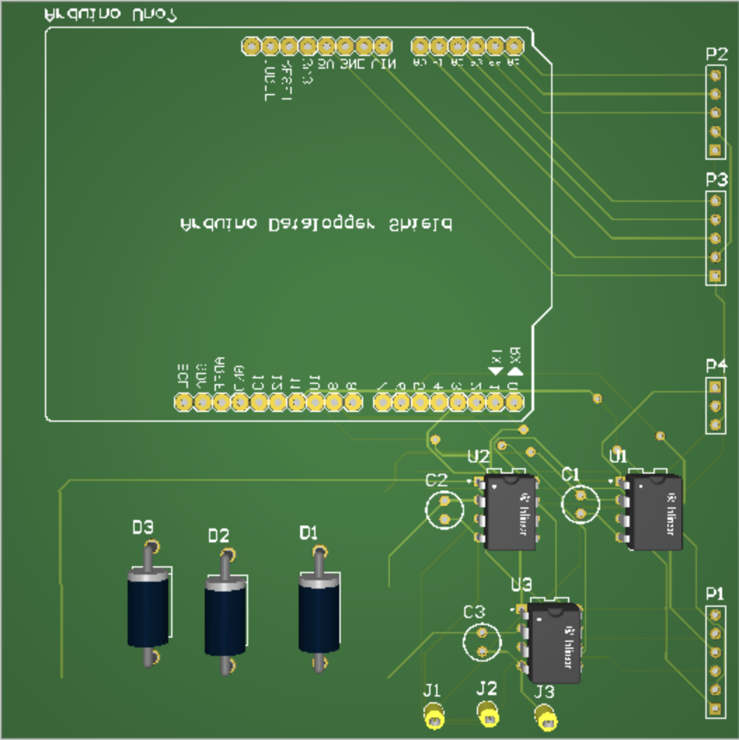
controller by designing the PCB layout using
Material Sourcing
A big challenge when planning our PCB design was ensuring that it could actually be
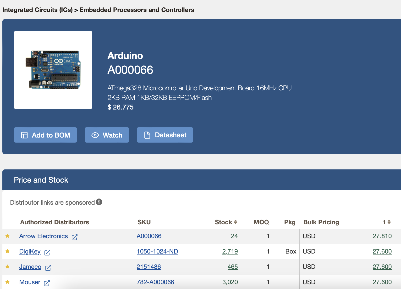
ordered (ie. the components were available). When transitioning from the initial layout
design to the PCB schematic and planning, we had to translate the generic components
(like diodes) to actual part numbers that could be readily sourced. Furthermore, it was
important to ensure our design cost much less than the
Redesign of PCB
As we further progressed with the design of the PCB, we realized that with the high voltage that we were dealing with (as high as 44V at times), the components we were using would not be able to sustain such high voltage. The decision was taken to split the PCB into 2 main sections: one responsible for power conversion (which would handle the high voltage) and the other part which would contain the rest of the components. This would streamline the design process and allow for the isolation of issues during testing.
Iterative Development
Over the 2 years working on the motor controller PCB, significant improvements were made with the design and functionality based on iterative development cycles. In 2025, a new PCB design was used focuing on optimizing the layout and components used in order to improve reliability and debuggability. The new design also focused on improving the efficiency of the motor through software. All motor controllers were controlled by microcontrollers running C++ code that managed the 3 phases of the motor via encoders and drivers.